CHARACTERISTICS
TECHNICAL SPECIFICATIONS OF PSR SECTIONAL SAMPLER
TU 3689-009-10524112-99
DEVICE AND OPERATING PRINCIPLE
The sampler (Fig. 2) consists of a **sight hatch 1**, **brackets 2**, **middle sections 3**, **lower bracket 4**, **upper section 5**, **guarding 6**, **drain valve with nozzle 7**, **lower section 8**, **control unit 9**, and **receiving unit 10**.
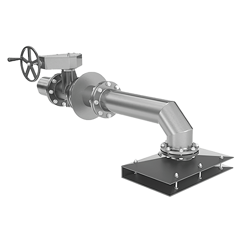
The pipelines of the **lower 8**, **middle 3**, and **upper 5 sections** are fastened together by means of **union connections (Fig. 1)**. The **lower section 8** is connected by a threaded fastener to the **drain valve and nozzle 7**. Sections **3, 5, 8** and the **drain valve with nozzle 7** form the sampling column, which serves as a drain.
The upper, middle, and lower sections are fastened to **brackets 2**, which are welded to the inside wall of the tank. The upper section is additionally fastened to the sight hatch crossbar, and the lower section to the **lower bracket 4**.
The drain valve with nozzle is fastened to the flange of the **receiving unit 10**.
The **sight hatch** consists of a body, lid, and gasket. A crossbar, to which the pipe of the upper section is fastened, is attached to the body with bolts and nuts. The sight hatch is mounted by welding into the tank roof.
Installation of the sampler sections is done through the sight hatch.
**Brackets 2** for fastening the sections are welded to the inside wall of the tank at intervals of 1000±1 mm.
The **middle section (Fig. 1)** consists of two **ball valves 3**, connected by a **pipe 5**. To the ball valves are fastened from below by thread **pipe 4 with coupling 1**, **bracket 2**, and from above **pipe 6**.
**Rocker arms 11** are fastened by pins to the axes of the ball valves, on which **rods 8 and 9** are installed using **axes 7**.
**Pin 10** is technological and is removed after the sampler is installed in the tank.
The **lower bracket 4 (Fig. 2)** of welded construction is installed on the bottom of the tank. The bracket is fastened to the base through a **compensator 11** with **studs 12**, **washers 13**, and **nuts 14**.
The **upper section** consists of a ball valve, to which pipes and brackets are fastened by thread from above and below.
A rocker arm is fastened to the axis of the ball valve, on which rods are installed using axes.
**Guarding 6** of welded construction is bolted to the **receiving unit 10**.

Fig. 1. Middle section of PSR sectional sampler:
1 — coupling; 2 — bracket; 3 — ball valve; 4, 5, 6 — pipe; 7 — axis; 8, 9 — rod; 10 — pin; 11 — rocker arm

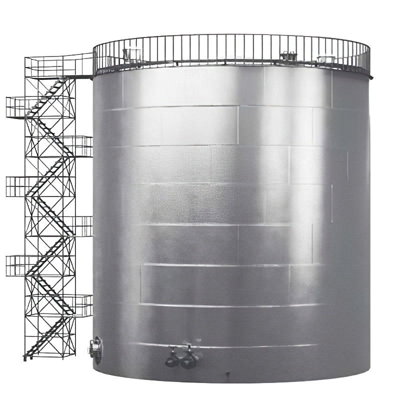
Fig. 2. PSR sectional sampler:
1 — sight hatch; 2 — bracket; 3 — middle section; 4 — lower bracket; 5 — upper section; 6 — guarding; 7 — drain valve with nozzle; 8 — lower section; 9 — control unit; 10 — receiving unit; 11 — compensator; 12 — studs; 13 — washers; 14 — nuts
The **drain valve with nozzle** consists of a drain valve, flange, pipe, and nut.
The **lower section** consists of two ball valves connected by a pipe.
To the ball valves of the lower section are fastened from below by thread an elbow, brackets, and from above — a pipe. Rocker arms are fastened to the axes of the ball valves, on which rods are installed.
The **receiving unit 10 (Fig. 2)** consists of a flange, stops, and is welded to the outer side wall in the lower part of the tank.
OPERATING PRINCIPLE
To take a sample, turn the handle of the **control unit 9 (Fig. 2)** to the right until it stops. The turning force is transmitted to the shaft through a coupling and pin connection to the lower rocker arm of the section. Rods of the lower, middle, and upper sections are pivotally connected to the rocker arm. By turning the rocker arms, the ball valves are opened or closed. The through-holes of the valves align with the side openings, simultaneously closing the upper and opening the lower openings of the bodies.
The product in the tank flows through the side openings of the ball valve bodies and fills the sections independently of each other.
When the control unit handle is turned all the way to the left, the through-holes of the balls align with the upper and lower openings of the bodies, blocking the side openings and isolating a sample column from the main product in the sampling column. The sample mixes and flows into a special sampling container.
The sample collected by the sampler, by isolating a column of product throughout the entire height of the tank and draining it through a system of pipes into a sampling container, corresponds in its composition to the product in the tank.
Sampling procedure:
· remove **guarding 6 (Fig. 2)**;
· open **valve 7**, drain remaining product from the sampling column into a container;
· close **valve 7**;
· turn the **control unit handle 9** to the right until it stops. Depending on the product's viscosity, wait from 15 seconds to 5 minutes;
· turn the **control unit handle 9** all the way to the left;
· open **valve 7**. Drain the sample into the sampling container;
· close **valve 7**. Secure **guarding 6** on **receiving unit 10**. Seal.
TECHNICAL SPECIFICATIONS
|
Parameter Name |
PSR Sectional Sampler |
|
Nominal bore diameter, mm |
15 |
|
Sample volume 1 m of sampling column, l |
0.150±0.005 |
|
Sample collection time, min, not more than |
5 |
|
Maximum product viscosity, cSt |
5.5 |
|
Parameter Name |
PSR Sectional Sampler |
|
Product temperature, °С: |
|
|
minimum |
–40 |
|
maximum |
+80 |
|
Hydrostatic pressure in tank, MPa, not more than |
0.16 |
|
Number of middle sections, pcs., not more than* |
7 |
|
Tank height, m, not more than |
18 |
|
Overall dimensions, mm, not more than: |
|
|
length |
710 |
|
width |
450 |
|
height* |
18100 |
|
Weight, kg, not more than* |
360 |
* The number of middle sections, height, and weight of the sampler are specified and agreed upon with the customer and depend on the tank height.
Number of sampler sections depending on tank height
|
Tank Height, m |
Sampler Designation |
Number of Sections |
||
|
lower |
middle |
upper |
||
|
17—18 |
PSR |
1 |
7 |
1 |
|
15—16 |
PSR–15 |
1 |
6 |
1 |
|
13—14 |
PSR–13 |
1 |
5 |
1 |
|
11—12 |
PSR–11 |
1 |
4 |
1 |
|
9—10 |
PSR–9 |
1 |
3 |
1 |
|
7—8 |
PSR–7 |
1 |
2 |
1 |
|
5—6 |
PSR–5 |
1 |
1 |
1 |
|
4 |
PSR–4 |
1 |
– |
1 special with two valves |
TOO SAMRUK KAZ is a modern industrial enterprise focused on: • Designing and developing engineering documentation for oil depots, tank farms, pipeline routes, various metal structures, and non-standard equipment; • Manufacturing metal structures, tanks, and vessels for various purposes (Vertical Steel Tanks (RVS), Horizontal Steel Tanks (RGS), Underground Tanks (UT)) in both above-ground and underground configurations with necessary equipment installation, as well as producing metal structures for buildings, constructions, railway overpasses, and supports for technological pipelines using various materials (alloyed and high-alloyed steel, stainless steel, aluminum alloys, etc.); The company has a logistics department that ensures a continuous construction cycle, allowing for the timely delivery of necessary equipment and machinery to the customer. Delivery is provided upon the customer's request as part of a comprehensive service package for the production and installation of tank and vessel equipment. The cost of services is calculated individually. You can learn more about TOO SAMRUK KAZ's production capacities in the "Production" section.
Year of foundation
tanks produced
vessels produced
metal structures produced
TOO SAMRUK KAZ is a manufacturer providing comprehensive supplies of tanks for various purposes, as well as tank equipment for the oil and gas, energy, chemical, and other industries.

The company has many years of experience in manufacturing and designing industrial equipment.

We utilize the most advanced industrial equipment for manufacturing and guarantee the highest quality of our products.

We deliver equipment on time. We have a well-established production and logistics structure.