SUPPORTS
**Pipeline supports** are significant elements of any communication system. They bear the weight of the pipes, and then the entire load is distributed to load-bearing structures or directly transferred to the soil. Supports allow pipes to be moved longitudinally, fixed, and protected from premature wear. Today, manufacturers offer a wide selection of communications and corresponding support elements made from various materials, all with their own technical characteristics.
The main function of pipeline supports is to **fix the communication in a specific position**. They also prevent pipe deformation due to temperature changes and vibrations. Vibrations often occur during the transportation of working media through the system.
It is crucial to pay utmost attention to the **installation process**, as the reliability of communications depends on the support elements. If errors are made, they simply will not cope with their assigned tasks.
In the case of a **gas pipeline**, particularly stringent requirements are placed on supports, especially when the pipeline runs through climatically unfavorable regions. It is equally important that the support structure protects the pipes from damage in the most vulnerable areas, i.e., at the fastening points.
The terminology of **GOST 22130** defines supports as a structural element of the pipeline; that is, they cannot be called a transitional structure between pipes and foundations.
Support elements are used in laying communications in various industries. The necessary products are selected depending on their purpose to allow for the transfer of axial, transverse, vertical loads, and torques to the soil or load-bearing structures.
Useful functions of this pipeline component:
· Protection of the pipe from damage at the point of contact with the structure.
· Ensuring the correct positioning of pipes.
· Distribution of load along the entire length of the structure and its transfer to the ground.
· Elimination of vibrations, reduction of stress in the system.
Support structures are divided into types based on:
· immobility/mobility;
· installation method.
By installation method, supports can be:
· suspended;
· conventional.
**Suspended models** are attached to ceiling slabs, plates, and in other ways. They are considered **movable pipeline supports**, meaning they can move in two directions: across or along the axis of the structure. In contrast, **fixed supports** have a different task – they rigidly secure the pipe in a specific position.
TYPES OF PIPELINE SUPPORTS
1. **HOUSING (CASED) SUPPORTS**.
To connect structural elements in space, a **box-shaped casing** is often used. It is made from sheet steel or welded from individual elements. Cased supports are mounted on a beam, have stiffening ribs, and are supplemented with pads, clamps, and U-bolts.
When using a casing, the pipe is raised by 100–200 mm, making it convenient to fasten and maintain during operation. Compared to the cost of bent angle and rolled metal products, purchasing the former is more cost-effective and reduces the overall cost of the structure.
2. **BODYLESS (FRAMELESS) SUPPORTS**.
This is a traditional model, which is a **cradle** made of sheet steel, bent to match the outer shape and diameter of the pipeline. Most often, this element is called a "pad." It can also be equipped with a round, strip, or band clamp and a base plate with holes for fastening.
The design is simple, requires a minimal amount of materials to manufacture, and consists of very few parts. For this reason, the bodyless model is considered the most affordable for pipeline construction. These support elements are marked as T11, HB, OPB.
3. **TUBULAR SUPPORTS**.
In terms of design, this element is a **vertically oriented nozzle** welded to a plate with mounting holes. To increase the contact area of the support nozzle with the pipeline, a saddle-shaped cut is made on its upper end using a laser or milling cutter, matching the shape of the main pipe.
The production of such models is based on **OST 36-146-88**. This type is suitable for pipelines with a diameter ranging from 57–630 mm and a media temperature up to +450 °C. Currently, there are four versions: A1, B1, A2, B2. These products are marked as TR and are manufactured using stainless steel, structural steel, and carbon steel.
4. **T-SECTION SUPPORTS**.
T-section elements can have different designs and are manufactured in two types:
· **Welded**. In this case, a piece of T-section is installed on a single flange, plates are welded to the ends, and a radial cut is made in their upper part corresponding to the pipe diameter for better pipeline fixation.
· **Clamped**. This refers to strip or band clamps that are welded over a piece of rolled metal, with holes for fasteners necessarily provided in its flange.
These types of T-section support structures are marked as TP and TH. Various methods of connecting pipeline elements can be chosen to achieve complete immobility of the joint or several degrees of freedom of connection.
5. **CLAMP SUPPORTS**.
These are found in both movable and fixed connection methods. The following types of fastening can be used:
· rod clamp;
· strip clamp;
· band clamp;
· flat clamp;
· U-bolt clamp;
· housing mount;
· with bodyless support structures;
· on welded and sliding pipeline supports;
· clamp used as a guide element.
The clamp securely grips the pipe from all sides, and can be used with dielectric and anti-friction gaskets. This fastening method can also achieve one degree of pipeline mobility along its axis.
The classic model is an inverted U-shaped structure with or without stiffening ribs.
Clamp elements are used for pipelines with diameters of 57–377 mm, while the U-bolt type is suitable for sizes 377–1420 mm. It is worth noting that assembly units may be marked differently due to the use of several standards in their production.
6. **WELDED SUPPORTS**.
Sliding and movable support structures are rigidly attached only to the base/posts or directly to both the base and the pipe. Welded support structures come in the following modifications:
· sliding guide;
· sliding fixed;
· steel;
· fixed;
· sliding;
· angle;
· on a beam with eyelets.
They are manufactured using rolled and bent angle, T-sections, channels, pipes, or bent, welded housings.
7. **SUPPORTS FOR VERTICAL PIPELINES**.
According to **OST 36-17-85**, supports for technological vertical pipelines and the strapping of technological lines are manufactured. Most often, this refers to a strip, rod, or U-bolt clamp, which is mounted on an angle bracket or in a bent housing.
In documentation, such structures are usually designated as VP, and they are typically fixed models. In this case, the main characteristics are material, diameter, construction length, temperature, and working medium pressure.
8. **U-BOLT SUPPORTS**.
A **U-bolt** is simply a type of clamp, supplemented with special fasteners or studs. U-bolt models are divided into types based on the design of the assembly unit and can be:
· tubular;
· strip;
· cased;
· stamped;
· stamped-welded.
The installation of this element is carried out as follows: the pipe is placed on a pad or cradle with holes for studs, and then the U-bolt is tightened over the threaded connections. To make it easier to clamp the pipe, special mechanisms, lugs, traverses, clamps, or beams can be used.
9. **ROLLER SUPPORTS**.
The design of this model stands out due to the following characteristics:
· two or more support surfaces are provided;
· installation is performed between bearing supports;
· axial displacement of the pipeline by a specified amount is allowed;
· lateral pipe displacement of up to 50 mm is allowed.
It is possible to manufacture single- and double-level elements, with one roller and several blocks, and enterprises also produce clamps for pipelines of energy facilities, steel and spring models. Rolling elements significantly reduce friction, and thus the wear rate of all structural elements. As a result, the service life increases, and assembly units are easier to repair.
10. **SIDE SUPPORTS**.
The design of this element includes a plate and a cradle, which must be equipped with several stiffening ribs for reinforcement. This model differs from the welded type only in its spatial arrangement, as it is attached to a vertical surface, thereby compensating for lateral loads but not bearing vertical forces.
Such elements are marked as T10 and are suitable for pipes with a diameter of 194–1420 mm.
11. **FRONT (THRUST) SUPPORTS**.
Considering the placement of front models relative to the working medium flow and pipe body, they are installed in a transverse projection. These products are typically divided into types based on manufacturing material and design:
· **shield-type** are made of reinforced concrete, often with multiple stiffening ribs;
· **thrust-type** represent a pair of stops in a vertical or horizontal plane on both sides of the pipeline, or they can be four stops on all sides.
Two-stop front elements are installed for small axial loads, while four-stop elements are necessary for significant loads. If necessary, the entire structure can be reinforced with half-rings and stiffening ribs.
12. **FIXED SUPPORTS**.
This type of structure is necessary when any movement of communications relative to supports and foundations must be prevented. Manufacturers offer the following versions designed for different operating conditions:
· "dead-end";
· for pipes in PUR thermal insulation;
· front and side thrust;
· U-bolt and clamp;
· cased and bodyless;
· for vertical ducts;
· reinforced thrust;
· reinforced concrete shield;
· welded and steel.
The abbreviation **NOP** is used to designate these pipeline elements. This type is suitable for installation with pipes ranging from 32–1420 mm in diameter and is designed for conditions with increased operational loads.
13. **MOVABLE SUPPORTS**.
If one or more degrees of pipeline mobility relative to the foundation or load-bearing structure are required, various movable models are used:
· clamp-type OPH;
· welded OPP;
· bodyless OPB.
The manufacturing rules for such pipeline supports are established by **GOST 14911-82, OSTs 36-94-83 and 36-146-88**. In addition, the technical specifications of individual enterprises, drawing albums T-MM-26-05, and other documentation are taken into account.
14. **SLIDING SUPPORTS**.
This type of movable element provides one degree of freedom in the axial direction. In this case, the following versions are available:
· steel and welded;
· bearing plates and in casings for pipes with PUR thermal insulation;
· for pipelines of thermal and nuclear power plants;
· with flat clamp and bracket;
· sliding fixed and guiding of several types;
· dielectric and U-bolt;
· clamp-type and bodyless.
To prevent rapid wear of pipes and system elements, anti-friction gaskets, rollers, and blocks are used.
15. **ADJUSTABLE SUPPORTS**.
They are chosen when precise vertical positioning of individual pipeline sections is required. Such structural elements must have movable wedge stops. Assembly units are marked with OR, and their manufacturing adheres to **TU 5263-003-93646692**. Another important element of such a support structure is the cradle. It is raised and lowered by moving the wedge stops, which are attached to the plate by bolted connections.
16. **DIELECTRIC SUPPORTS**.
These elements are necessary to protect the pipeline from stray and induced currents. For this purpose, a gasket made of any dielectric material, such as paronite with anti-friction qualities, is used.
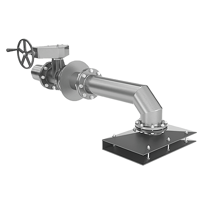
17. **SUPPORTS FOR FITTINGS**.
**OST 36-17-85** establishes norms for the production of structures for installing pipeline fittings **OKA**. From a technical point of view, these are four stiffening ribs cross-welded together and mounted on a base plate. In their upper part, the stiffening ribs follow the outer contour of the pipeline fitting being installed.
18. **UNLOADING SUPPORTS**.
This structure is necessary to compensate for water hammer, vibrational, and mechanical loads, which are unavoidable during the operation of pumping and compressor equipment. This element consists of a nozzle and has several degrees of freedom relative to the foundation. Its production is based on **SNiP 3.05.05-84**, and it is marked **GPA**.
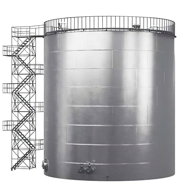
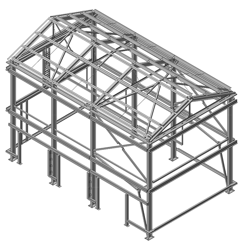
TOO SAMRUK KAZ is a modern industrial enterprise focused on: • Designing and developing engineering documentation for oil depots, tank farms, pipeline routes, various metal structures, and non-standard equipment; • Manufacturing metal structures, tanks, and vessels for various purposes (Vertical Steel Tanks (RVS), Horizontal Steel Tanks (RGS), Underground Tanks (UT)) in both above-ground and underground configurations with necessary equipment installation, as well as producing metal structures for buildings, constructions, railway overpasses, and supports for technological pipelines using various materials (alloyed and high-alloyed steel, stainless steel, aluminum alloys, etc.); The company has a logistics department that ensures a continuous construction cycle, allowing for the timely delivery of necessary equipment and machinery to the customer. Delivery is provided upon the customer's request as part of a comprehensive service package for the production and installation of tank and vessel equipment. The cost of services is calculated individually. You can learn more about TOO SAMRUK KAZ's production capacities in the "Production" section.
Year of foundation
tanks produced
vessels produced
metal structures produced
TOO SAMRUK KAZ is a manufacturer providing comprehensive supplies of tanks for various purposes, as well as tank equipment for the oil and gas, energy, chemical, and other industries.

The company has many years of experience in manufacturing and designing industrial equipment.

We utilize the most advanced industrial equipment for manufacturing and guarantee the highest quality of our products.

We deliver equipment on time. We have a well-established production and logistics structure.